A solar array can produce less power, become difficult to service, or require costly removal when the roof, electrical design, access routes, and maintenance plan are treated as afterthoughts. You will be able to turn a site inspection, electricity-use record, and equipment specification into an installation plan with defined tests, service intervals, replacement provisions, and performance measures.
Key takeaways
- Confirm roof life, waterproofing, structural capacity, and maintenance access before sizing the array.
- Size generation against measured loads, operating schedules, storage needs, and future demand.
- Specify protection, monitoring, labels, and replaceable components before procurement.
- Record test results, equipment details, warranties, and maintenance triggers at commissioning.
Start with the roof, site conditions, and future access
A suitable site is not simply a roof that can carry module weight. It must support the array, preserve waterproofing, and remain inspectable until planned replacement. Begin with a documented solar site assessment that treats roof life and maintenance access as design constraints.
Measure usable roof area after marking setbacks, skylights, drainage paths, fragile coverings, fire-service routes, and safe walking zones. Record roof age, construction, load path, attachment locations, wind uplift, snow or seismic demand, and corrosion exposure; obtain an engineer’s confirmation when the structure or fixing method is uncertain.
Complete a roof waterproofing inspection before drilling or ballasting. If the covering could require replacement during the array’s service life, replace or rehabilitate it first, or budget for array removal and reinstallation. Otherwise, a leak can become a warranty dispute and a major maintenance event.
Record shading at different times of day and across seasons, including shadows from nearby trees and buildings. Check whether trees can grow into the array’s path, and allow for future trimming without damaging modules or restricting roof access.
Confirm that technicians can reach the equipment without stepping on modules or dismantling the array. Preserve clear routes to:
- Inverters, disconnects, and combiner boxes
- Roof inspection zones and drainage paths
- Required fire-service routes
- The main distribution board
Route cables so they do not form unsupported loops, rub against the roof, collect standing water, or sit in drainage and snow-sliding paths. The design is suitable only when its attachment, access, shading, and waterproofing decisions remain workable for the system’s full service life.
Size the array and choose the system around real operating needs
Use 12 months of electricity bills to calculate average daily energy, then separate daytime consumption from evening and overnight demand. The connected load indicates the maximum simultaneous demand and helps size the inverter; it does not tell you how much energy the array must produce.
Estimate array capacity by dividing target daily kilowatt-hours by the site’s peak-sun-hours figure, then allowing for inverter, temperature, wiring, soiling, shading, and other system losses. Check the result against roof orientation, tilt, local solar conditions, and future load growth.
Size the battery from the energy required by the backup circuits, not from the entire connected load: usable battery capacity must cover their kWh demand for the required outage duration after depth-of-discharge and conversion losses.
| System choice | Design basis | Best fit |
|---|---|---|
| On-grid | Array supplies daytime loads; surplus follows the approved export rules; grid supplies shortages. | Reliable grid, low backup requirement, lowest battery cost |
| Hybrid | Grid, array, and battery share an inverter; controls reserve charge for selected backup circuits. | Regular outages, time-of-use savings, or limited backup demand |
| Battery-backed | Battery and inverter support defined loads during outages, with sufficient autonomy and recharge capacity. | Costly interruptions, weak grids, or essential loads that cannot stop |
Check the DC design at the coldest expected module temperature. Cold-weather open-circuit voltage must remain below the ratings of the modules, inverter, conductors, disconnects, and surge protection; nominal module voltage is not a safe substitute for that calculation.
Specify the electrical design for safety, monitoring, and replacement
Specify every component by its electrical limits, measurement points, and replacement path—not by brand name alone. DC cable sizing must account for continuous current, ambient temperature, grouping, voltage drop, UV exposure, and the installation method. Undersized or overheated cable creates losses and insulation damage that a meter may not reveal.
Calculate cold-temperature voltage using the lowest expected module temperature, because open-circuit voltage rises as cells cool. Confirm the maximum string voltage stays below the ratings of the modules, inverter, conductors, disconnects, and surge protection devices. Document string configuration, fuse ratings, polarity checks, earthing, and accessible DC and AC isolators.
- Specify modules with PID resistance suited to the site’s humidity, temperature, system voltage, and grounding arrangement; require inverter insulation monitoring and a defined response to an insulation fault.
- Route cables on UV-resistant supports without unsupported loops, roof abrasion, standing water, or connectors in drainage and snow-sliding paths.
- Provide string fuses, correctly rated disconnects, type and location of surge protection devices, and test points that technicians can reach without removing modules.
- Reserve replacement paths for fuses, surge cartridges, connectors, sensors, communication hardware, inverter fans, and filters; record an approved substitute for discontinued proprietary parts.
| Monitoring choice | What it reveals | Specification to require |
|---|---|---|
| Whole-system meter | Total production only | Revenue-grade energy measurement |
| Inverter-input monitoring | Failed string, fuse, or connector | String current and voltage records |
| Plant monitoring with sensors | Underperformance after weather adjustment | Irradiance and module-temperature inputs, alarms, and downloadable history |
Make procurement and commissioning produce a usable handover record
Require a handover pack that lets a new technician verify, operate, and support the system without relying on installer memory. Put deliverables in the purchase order and make final payment conditional on complete records; IEC 62446-1 provides a useful baseline, but it does not automatically define every test you need.
- An as-built single-line diagram showing array sections, string IDs, isolators, fuses, surge protection, earthing, inverter, meter, and distribution-board connections.
- A string schedule with module count, cable sizes, connector routes, serial numbers, inverter model, firmware, protection ratings, and configured limits.
- Module and inverter datasheets, installation and operating manuals, warranty contacts, administrator-transfer instructions, and replacement-part references.
- Signed commissioning tests recording conductor continuity, polarity, open-circuit voltage, short-circuit or operating current, insulation resistance, protective-device ratings, grounding and bonding, and inverter startup, shutdown, alarms, and grid interaction.
- Roof and array photographs showing concealed cable routes, labels, attachment points, and equipment locations.
Specify whether I-V-curve tracing, thermal imaging, earth-electrode tests, or other diagnostic work is included; IEC 62446-1 distinguishes baseline verification from additional testing. Ask Rupribha Electricals (OPC) Private Limited to tie any supplied on-grid or hybrid inverter to the exact string schedule and final settings, not merely provide catalog sheets.
Store digital and paper copies with test dates, instrument serial numbers, calibration dates, installer details, and the commissioning sign-off. Record who receives passwords and who can approve warranty claims, because an undocumented system turns a simple fault into a site investigation.
Related products
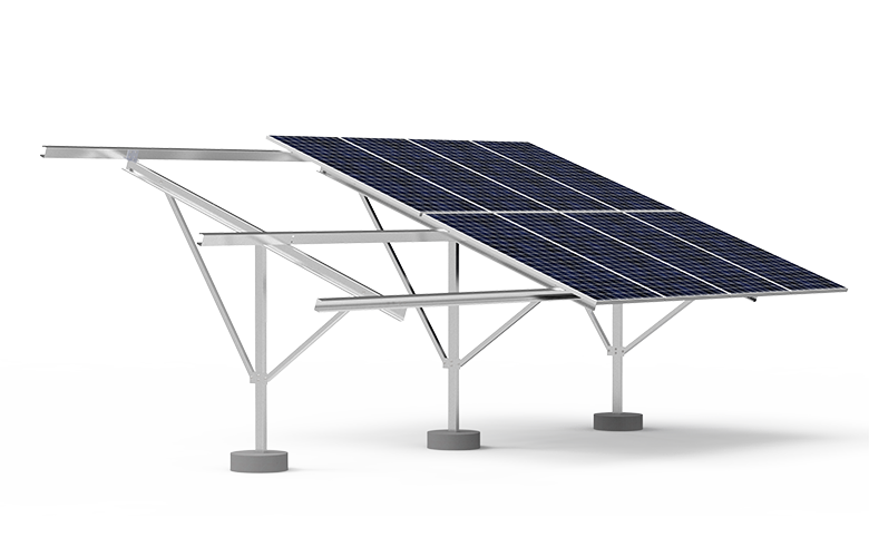 | Plant BOS Solar structures are essential components for supporting solar panels, ensuring their stability and optimal performance. View product → |
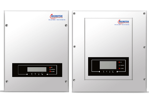 | Solar Products A Solar Ongrid Inverter efficiently converts solar energy into usable electricity, directly feeding it into the grid. View product → |
Run maintenance by condition, measured output, and planned replacement
Record the commissioning baseline before handover: energy from each inverter input or string, irradiance, module temperature, operating voltage, and fault status. Compare later readings with weather-adjusted expectations, not just whole-plant meter totals; this reveals a failed string, blown fuse, loose connector, or tracker fault before the monthly bill exposes it.
Use a condition-based schedule alongside routine checks:
- Each month, review the inverter fault log, communication status, string-level output, and abnormal energy trends.
- Each quarter, inspect cable supports, connector housings, drainage paths, roof penetrations, ventilation openings, and accessible fasteners without stepping on modules.
- Clean modules when measured soiling reduces production enough to justify the work. Base the trigger on local dust, bird activity, rainfall, water quality, and cleaning cost; high-pressure washing or aggressive brushing can damage glass, coatings, seals, and connectors.
- Perform a thermal inspection after the first operating season and after any persistent output anomaly. Hot connectors, fuses, terminals, and bypass-diode areas require investigation, not simply a reset.
Make spare-parts planning part of the handover. Keep fuses and surge-protection cartridges matched to the design, retain approved connectors and communication hardware, and document replacements for serviceable inverter fans or filters. Specify a replacement path if the inverter, sensor, or communications device is discontinued.
Budget roof replacement before installation if the roof will not outlast the array. Otherwise include safe array removal, storage, reinstallation, testing, and waterproofing in the lifecycle plan.
Frequently asked questions
What site conditions must you check before installing rooftop solar?
Check structural capacity, remaining roof life, waterproofing, shading, drainage, cable routes, equipment locations, and safe access for inspection and replacement.
How should you size a solar panel system?
Use measured electricity demand, load profiles, operating schedules, available roof area, grid limits, storage requirements, and expected future loads.
What should the electrical design include?
Specify DC and AC isolation, overcurrent protection, surge protection, earthing, cable ratings, inverter monitoring, labels, and access for component replacement.
What records should you receive after commissioning?
Request the as-built layout, single-line diagram, equipment serial numbers, test results, protection settings, warranties, manuals, and monitoring credentials.
How should solar system maintenance be planned?
Use inspection schedules, measured output, inverter alarms, thermal or visual checks, cleaning conditions, and planned replacement dates to trigger work.
Related products
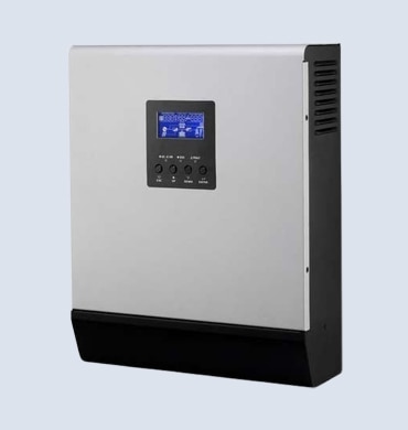 | Solar Products A Solar Hybrid Inverter seamlessly combines solar energy, battery storage, and grid power for efficient energy management. View product → |
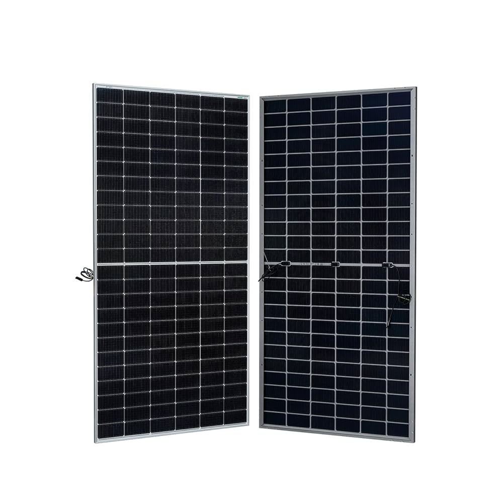 | Solar Products Our **Solar Monocrystalline Module** offers high efficiency, durability, and superior performance, even in low-light conditions. View product → |
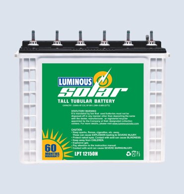 | Solar Products Solar Tubular Batteries are high-performance energy storage solutions designed for solar power systems. View product → |
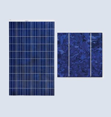 | Solar Products Solar Polycrystalline Modules are efficient and cost-effective solar panels made from multiple silicon crystals. View product → |