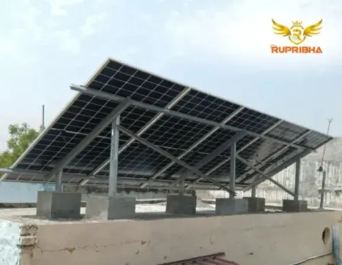

A roof can have enough visible space for solar panels and still reject the proposed layout because of shade, weak attachment points, drainage, electrical limits, or poor access. A proper assessment converts those conditions into a documented design: the usable array area, module arrangement, inverter and string plan, structural method, and installation responsibilities.
Key takeaways
- Inspect roof condition, load capacity, access, drainage, and obstructions first.
- Measure usable roof area after accounting for shade, setbacks, and service pathways.
- Match array size to household demand, inverter limits, and future electricity use.
- Choose mounting hardware that suits the roof and protects waterproofing.
What must be inspected before a rooftop layout is accepted?
A rooftop layout is not ready for a panel count until a full rooftop assessment confirms the roof’s condition, structure, access, and obstructions.
Walk the entire roof and record the slab or framing type, visible cracks, damp patches, ponding water, corrosion, loose finishes, parapet height, stair headroom, water tanks, vents, skylights, existing solar equipment, drainage outlets, and safe access routes.
- Photograph every obstruction and mark its location and height on a roof plan.
- Complete a documented load-path review for module dead loads, rail reactions, ballast, wind uplift, snow loads, and existing equipment. A visual roof check or module load rating cannot prove that the framing and attachments are adequate.
- Record anchor locations, reinforcement information, drilling restrictions, and roof warranty conditions. Inspect the roof waterproofing membrane, flashing, old penetrations, and sealant joints before proposing new penetrations.
Roof condition also affects procurement. If replacement is approaching, installing solar first can create removal and reinstallation costs.
Roof waterproofing and structure determine the solar mounting structure selection:
| Option | Suitable decision | Main concern |
|---|---|---|
| Penetrated | Structure and membrane support approved anchors | Flashing, leakage, and warranty |
| Ballasted | Drilling is restricted and roof capacity allows ballast | Concentrated weight and wind uplift |
| Non-penetrating | Penetrations or ballast are unsuitable | Engineering capacity and restraint |
The survey must conclude whether the roof is ready, needs repair, or requires a different mounting method.
How do roof measurements, shade, and orientation determine usable solar area?
1. Measure every roof plane, ridge, eave, parapet, obstruction, access path, and equipment zone. Convert gross roof area into usable roof area by subtracting required setbacks, maintenance clearances, fire-service access, tanks, vents, skylights, stair structures, and shaded sections.
A tape measure and marked roof plan prevent a large but unusable dimension from becoming a false panel count.
2. Record the module’s length and width in the proposed orientation before calculating capacity. Portrait and landscape layouts change solar panel spacing, row gaps, and the leftover strips around parapets and obstructions. Count only the modules that fit inside the remaining footprint.
3. Perform a rooftop shade analysis for parapets, neighbouring buildings, trees, overhead cables, tanks, and stair structures during morning, midday, and afternoon visits. Repeat those observations in summer and winter, or use a solar-path and obstruction-horizon tool; the lower winter sun casts longer shadows.
A shaded roof can lose production even when its annual sunlight score looks strong.
4. Model the proposed plane of array using its tilt and azimuth, rather than applying one site-wide sunlight figure. An unshaded south-facing roof can maximise annual yield, while an east-west arrangement can suit a shallow roof, morning-and-afternoon household demand, or tighter row spacing where self-consumption matters more than midday output.
Include Delhi’s heat, dust, monsoon soiling, roof obstructions, temperature, wiring, mismatch, availability, and inverter losses in the generation estimate.
How does the survey match the array to the home’s electrical demand?
A roof can fit the planned modules and still fail the home electrically. Start with electricity bills or interval data, then compare daytime consumption with expected generation and record future loads such as an electric vehicle, heat pump, induction cooking, or additional air-conditioning.
Collect these items before choosing solar inverter sizing:
- Sanctioned load, main incomer rating, service voltage, and whether the home has single-phase or three-phase supply
- Distribution-board layout, busbar and conductor ampacity, conductor sizes, meter arrangement, disconnect locations, and utility interconnection limits
- Grounding and bonding condition, available fault current, and whether export-limiting controls or a service upgrade is needed
Check the inverter’s continuous rating against the service rating and connection method. A 120% busbar calculation is not blanket permission for a load-side connection; confirm the applicable NEC edition, equipment listing, conductor protection, NEC 705.12 rules, utility, and authority requirements.
Determine module count from the measured footprint, then test every string for cold-weather maximum open-circuit voltage and hot-module minimum operating voltage against the inverter’s voltage and MPPT ranges.
| Design | Advantage | Cost or risk to compare |
|---|---|---|
| String inverter | Fewer rooftop electronics | Shade and mixed roof planes can reduce output |
| Optimizers | Module-level shade control | More devices, communications, replacements, and heat exposure |
| Microinverters | Suits mixed orientations | More rooftop electronics and harder access |
For backup power, add backed-up loads, transfer equipment, battery location, clearances, ventilation, thermal management, emergency access, and applicable fire and electrical-code checks.
How should the assessment choose the mounting method and prevent roof damage?
Choose the mounting method only after checking roof strength, slope, membrane condition, wind zones, perimeter and corner uplift, ballast concentration, maintenance access, and local wind and snow criteria. A ballasted solar structure suits some roofs; a non-penetrating solar mounting system suits others.
| Method | Main load or risk | Check before approval |
|---|---|---|
| Penetrated | Anchor uplift and water entry | Framing, anchor positions, flashing and drainage |
| Ballasted | Concentrated dead load and sliding | Roof capacity, slope, ballast layout and access |
| Other non-penetrating | System-specific restraint | Manufacturer design, wind zones and roof warranty |
A module or rail rating does not prove that the building framing or anchors resist uplift. Snow review must include drifting, sliding, roof slope, array position, and simultaneous roof and photovoltaic loads; wind review must address higher perimeter and corner uplift.
For every penetration, document the anchor location, roof penetration flashing, compatible sealant, drainage path, and inspection responsibility before drilling. State who repairs drilling-related leakage, the workmanship coverage period, and whether the roof warranty remains valid.
Measure solar conduit routing from the array to the inverter and service panel. Long or obstructed routes change conductor size, voltage drop, labour, isolation points, and future servicing. Place the inverter away from damaging heat and rain, with required clearance and working access. These details explain why equal module counts can produce different balance-of-system costs.
What should the site survey report contain before you approve the design?
Approve the design only when the solar site survey report lets you trace every number back to a measurement, photograph, bill, or stated assumption.
1. Require a dated report naming the address and surveyor. It must include a roof plan with north arrow, dimensions, parapet and obstruction heights, photographs, slab or framing observations, waterproofing condition, shade notes by time and season, and marked exclusion zones.
2. Check the electrical pages for bills or interval data reviewed, sanctioned load, service and incomer ratings, busbar and conductor ampacity, phase configuration, meter and disconnect locations, available fault current, grounding and bonding observations, inverter location, conductor route, and every utility or service-upgrade assumption.
3. Check the proposed solar layout for module dimensions and count, row spacing, tilt, azimuth, string arrangement, equipment clearances, mounting type, anchor or ballast zones, and estimated losses. The yield model must use that plane of array and state temperature, soiling, mismatch, wiring, availability, and inverter losses.
4. Require a shade report that identifies obstructions and records inaccessible areas, unverified structural capacity, future loads, repairs, and pending utility approvals. It should also flag snow, wind, roof-load, rapid-shutdown, and export-limiting assumptions where they apply.
5. Obtain homeowner installation approval for the layout, visible equipment, drilling or ballast method, access route, shutdown periods, and leakage responsibility. Rupribha Electricals (OPC) Private Limited is one supplier you can ask to show this evidence; the report matters more than brand or headline wattage.
Related product
 | Plant BOS Solar structures are essential components for supporting solar panels, ensuring their stability and optimal performance. View product → |
Frequently asked questions
What must be inspected before a rooftop solar layout is accepted?
Inspect roof age and condition, structural capacity, waterproofing, access, drainage, parapets, vents, tanks, skylights, overhead lines, and fire or maintenance pathways.
How do measurements, shade, and orientation determine usable solar area?
Measure roof planes and setbacks, map obstructions, record shade across the day, and assess orientation and tilt before calculating the panel area that can produce reliably.
How does the survey match the array to a home's electrical demand?
Review electricity bills, load patterns, sanctioned load, available roof area, inverter capacity, and future demand before selecting the system size.
How should the assessment choose the mounting method and prevent roof damage?
Match rails, brackets, ballast, or anchored frames to the roof material and structure, then specify waterproofing details, drainage clearance, wind resistance, and cable protection.
What should a site survey report contain before approving the design?
Require measurements, photographs, shade findings, roof and structural observations, electrical data, proposed layout, equipment assumptions, mounting details, cable routes, risks, and unresolved approvals.